Abstract
To address the issue where the existing flow control valve in a turbine guide shoe is prone to the simultaneous opening of dual flow channels at low flow rates—allowing drilling fluid containing lost circulation material (LCM) to enter and clog the turbine—a novel flow control valve structure based on the linkage control of the valve core's axial displacement was designed. This structure synchronously regulates the opening and closing of the radial and conical flow channels through the axial movement of the valve core, structurally eliminating the risk of both flow channels opening simultaneously. A force model of the valve core was established, and numerical simulations of the internal flow field under various flow rate conditions were performed using ANSYS Fluent. The results indicate that as the flow rate increases from 10.6 kg/s to 21.2 kg/s, the fluid thrust acting on the valve core in the open state rises from 394 N to 1557 N, which effectively overcomes the spring preload to drive the valve core downward for closure. As the flow rate increases from 21.2 kg/s to 26.5 kg/s, in the closed state of the valve core, even without accounting for the pressurization effect of the downstream turbine on the fluid, the force acting on the valve core ranges from 581 N to 905 N—significantly exceeding the maximum force of 394 N in the open state—thereby ensuring stable and reliable flow channel switching. The pressure distribution of the flow field demonstrates that the flow field remains generally stable in the closed state at high flow rates; however, in the open state at low flow rates, a localized vortex low-pressure zone forms at the top of the valve core and induces a certain degree of jet deflection, though its impact on the overall flow performance is limited. The research results validate the rationality of the novel flow control valve design.
Keywords
turbine guide shoe flow control valve flow channel switching design simulation
1. Introduction
With the rapid development of China's industry, the demand for fossil energy such as oil and gas continues to grow, and the number of horizontal and extended-reach wells developed has increased significantly. However, problems such as increased well depth, complex formations, drilling difficulties, and casing being stuck or failing to reach the bottom during running have become increasingly prominent [1][2]. To cope with these difficulties, during shale oil drilling in Dagang Oilfield in 2019, Wang Peng et al. successfully tackled the problems using methods such as turbine guide shoes. Without the need to rotate the casing, this tool can effectively resolve sand bridge and borehole necking issues, improve wellbore quality, and eliminate the need for tripping [3], making it a preferred choice for domestic and foreign enterprises.
Both domestic and foreign researchers have actively explored turbine guide shoe tools. Among them, ADMA-OPCO and Weatherford jointly developed a free-rotating eccentric casing shoe capable of passing through obstacles on its own without rotating the casing string [4][5]; Deep Casing Tools and Gotech developed a drilling-fluid-motor-driven turbine casing shoe powered by a turbine motor to drive a rotating reamer for hole cleaning and enlargement [6][9]; Han Fei et al. developed a string-running tool using a turbine to drive cemented carbides on the outer wall of the casing shoe for hole expansion [10]; and Li Shekun et al. developed a downhole turbine-driven oscillating-rotating casing guide shoe, which utilizes an oscillation sub to reduce casing running friction and improve cementing quality [11][12]. Furthermore, Feng Ding et al. developed a hydraulically driven reaming guide shoe tool that uses a novel baffle block to alter the drilling fluid flow rate, generating different torques on the turbine shaft to enhance the casing running speed [13], as well as a drillable adaptive turbine guide shoe tool utilizing an adaptive boosting assembly and a power casing shoe assembly to resolve the problem of failing to run the casing effectively when sand bridges or borehole necking occur in the wellbore [14]. Luo Guangfu et al. used the finite element method to perform single-factor sensitivity analysis and screened out key parameters affecting the hydraulic efficiency and maximum equivalent stress of the turbine [15].
However, domestic research on the "adaptive diversion mechanism of turbine guide shoes for drilling fluids at different flow rates" remains insufficient. When facing low-pressure or highly fractured formations, lost circulation materials (LCM) must be added to the drilling fluid to enhance well-leakage resistance; however, the turbine is prone to being jammed or clogged by lost circulation materials in low-flow-rate environments. Deep Casing Tools added a flow-rate-sensing adaptive diversion function to its safety valve, which selectively directs drilling fluid into different channels by changing the flow rate, hence referred to as a flow control valve [16][18]. Nevertheless, this design still entails the risk of dual flow channels opening simultaneously, allowing lost circulation material to enter the turbine. Therefore, a novel flow control valve structure based on the linkage control of the valve core's axial displacement is proposed, and the rationality of its force characteristics and flow field variation laws under various working conditions is verified through fluid simulation.
2. Working Principle and Structural Design
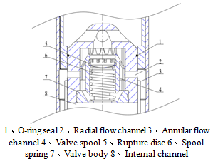
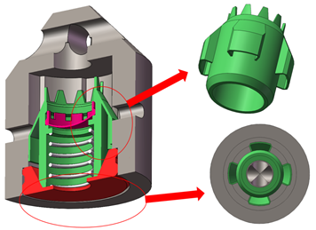
As the core diversion mechanism of the turbine guide shoe tool, the flow control valve is used to activate the turbine on demand when the casing running encounters obstruction. Its structural design is illustrated in Figure 1 and 3, primarily consisting of a valve seat, valve core, valve spring, valve body, and rupture disc. Guide slots are arranged on the inner wall of the valve body to restrict the valve core to vertical linear motion only. Four radial flow channels are provided on the guide slots, connecting to the inlet leading into the annular flow channel; the vertical movement of the valve core controls the opening and closing of these radial flow channels. The flow channel between the valve core and the valve seat is designated as the conical flow channel, and the vertical movement of the valve core similarly controls its opening and closing. Under both low and high flow rate conditions, the radial flow channel and the conical flow channel cannot be opened or closed simultaneously. In the turbine shutdown state (low flow rate condition), the drilling fluid velocity is low, and the valve spring relies on its preload force to push the valve core upward, keeping the conical flow channel between the valve core and the valve seat open so that the drilling fluid enters the internal channel via the conical flow channel. In the turbine working state (high flow rate condition), the drilling fluid velocity increases, and the flow control valve core overcomes the spring force under the action of fluid differential pressure to move downward and seal against the valve seat, closing the central conical flow channel while opening the radial flow channels, thereby directing the drilling fluid into the annular flow channel to power the turbine.
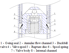
The structure of the conventional flow control valve is illustrated in Figure 2. The opening and closing of the annular flow channel and the conical flow channel rely respectively on the deflection deformation of the duckbill valve and the axial displacement of the valve core, with no absolute linkage between their states. This can lead to a state where both the annular and conical flow channels open simultaneously during actual operation, which reduces the power generated by the turbine and introduces the risk of clogging the turbine at low flow velocities. The flow control valve structure shown in Figure 1 successfully avoids this phenomenon by integrating the control of the opening and closing of both flow channels into the axial displacement of a single valve core, fundamentally eliminating the potential hazard of simultaneous dual-channel opening from a mechanism design principle.
3. Force Analysis of the Valve Core
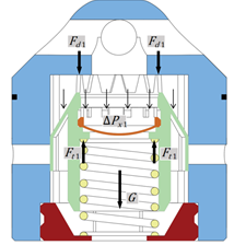
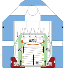
To thoroughly analyze the start and stop functions of the turbine guide shoe realized by adjusting the flow rate, this paper takes the product data of a 9-5/8-in. guide shoe from an international company as the calculation basis. The fluid flow within the turbine drilling tool is generally turbulent. The relevant product data of the turbine guide shoe are presented in Table 1:
| Inner radius of annular flow channel | Outer radius of annular flow channel | Maximum pressure drop | Low flow rate | High flow rate |
| 0.10875m | 0.134m | 4.4MPa | 0~0.0106m3/s | 0.0212~0.0265m3/s |
As shown in Figure 4, when the turbine is shut down, the valve core is in the open state, with the radial flow channel closed and the conical flow channel open. To thoroughly understand the force state of the valve core, it is necessary to investigate the relationship between the fluid velocity and the pressure difference across the flow control valve. The force formula for the valve core is expressed as:
∆ P x 1 A p 1 + G + F d 1 = F t 1 (1)
Where: ∆ P x 1 is the total pressure difference across the valve core in the open state, Pa; F t 1 is the upward reaction force of the spring on the valve core when open, N; F d 1 is the upward reaction force of the upper wall of the flow control valve on the valve core, N; A p 1 is the effective area subjected to the force on the valve core, m2; G is the gravity of the valve core.When the flow rate increases such that ∆ P x 1 A p 1 + G + F d 1 > F t 1 , F d 1 drops to 0 ,and the valve core accelerates downward to open.
As shown in Figure 5, when the turbine is working, the valve core is in the closed state, with the radial flow channel open and the conical flow channel closed. The force acting on the valve core mainly originates from the front-and-back pressure difference generated by the operation of the turbine drilling tool, and its force formula is:
∆ P x2 A p2 +G= F t2 + F d2 (2)
Where: ∆ P x 2 is the total pressure difference across the valve core in the closed state, Pa; F t 2 is the upward reaction force of the spring on the valve core, N; F d 2 is the upward reaction force of the lower wall of the flow control valve on the valve core when closed, N; A p 2 is the effective area subjected to the force on the valve core, m2;Ensuring F d 2 > 0 is required to guarantee that the valve core can be securely locked in the closed position.
4. Simulation Analysis
4.1 Model Extraction and Simplification
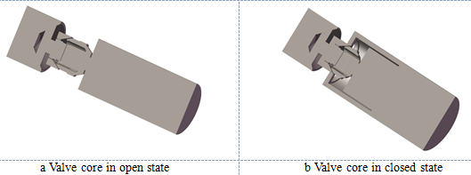
Based on the structure of the flow control valve shown in Figure 1, after extracting the internal fluid domain using Solid Works, a reasonable geometric simplification was performed on the fluid domain while ensuring that the main flow characteristics remained unchanged. Minor fillets, chamfers, return spring solids, and irregular micro-gap fluid domains at component joints were removed, and the fluid channel at the outlet was extended; the resulting model is shown in Figure 6 . In Figure 6b, the annular flow channel—which communicates with the turbine power section in the actual assembly—is connected to the internal channel in advance. The purpose of this arrangement is to investigate whether the valve core can achieve stable opening under the pressure difference generated by itself at high flow rates, thereby avoiding the scenario where both the radial and conical flow channels are in a semi-open state during actual operation.
4.2 Mesh Generation and Boundary Condition Settings
(1)Mesh Generation
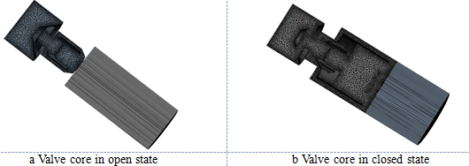
Mesh generation was conducted using ANSYS Fluent. A hexahedral mesh was adopted for the cylindrical fluid domain at the outlet, and a tetrahedral mesh was used for the internal fluid domain of the flow control valve, with a uniform mesh size of 5 mm. The total mesh count and average mesh quality are 411,842 and 0.8816 for Figure 6a, and 919,244 and 0.8785 for Figure 6b, respectively, which satisfy the requirements of fluid simulation calculations. By comparing the variation rates of the inlet-outlet pressure drop and the force acting on the valve core under mesh sizes of 8 mm, 6 mm, 5 mm, 4 mm, and 2 mm—all of which were below 5%—the mesh independence verification was successfully passed.
(2)Boundary condition settings
The inlet was set as "mass inlet" and the outlet as "outlet". A steady-state calculation was selected with the number of iterations set to 150. The Realizable k-ε model was chosen as the turbulence model, and a second-order upwind scheme was adopted for the solution to reduce calculation errors. The fluid medium was set as incompressible liquid water. Force monitoring surfaces were established for the faces associated with the valve core, and pressure monitoring points were set at the inlet and outlet to check whether the simulation converged.
4.3 Flow Field Analysis of the Flow Control Valve
Mass inlet values of 10.6 kg/s and 21.2 kg/s were set for the fluid domain with the valve core in the open state, and 21.2 kg/s and 26.5 kg/s were set for the fluid domain with the valve core in the closed state, in order to observe the force acting on the valve core and the pressure distribution within the fluid domain.
(1)Force Condition of the Valve Core
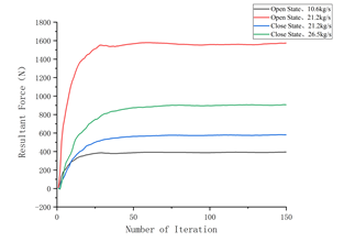
As shown in Figure 8, as the number of iterations increases, the force acting on the valve core generated by the pressure difference between its upper and lower surfaces rises rapidly in the early stage of iteration and subsequently stabilizes, indicating that the simulation has converged. With the valve core in the openSS state, when the inlet fluid enters the flow channel at flow rates of 10.6 kg/s and 21.2 kg/s, the forces acting on the valve core are 394 N and 1557 N, respectively. Given that 10.6 kg/s is the maximum allowable flow rate in the low flow rate range and 21.2 kg/s is the minimum flow rate in the high flow rate range, the difference in the vertically downward force exerted by the fluid on the valve core reaches up to 1163 N. This ensures that the valve core can be effectively driven at high flow rates to move downward and block the conical flow channel. With the valve core in the closed state, when the inlet fluid enters the flow channel at flow rates of 21.2 kg/s and 26.5 kg/s, the forces acting on the valve core are 581 N and 905 N, respectively. Even without considering the influence of the turbine on the pressure difference across the valve core, the force acting on the valve core remains significantly higher than the maximum force of 394 N in the stable open state. This guarantees that during the downward movement of the valve core, the conical flow channel and the radial flow channel will not be simultaneously open when the valve core stabilizes, thereby improving the opening and closing reliability of the valve core.
(2)Pressure Distribution
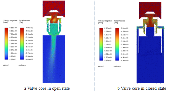
Figure 9a shows the pressure and velocity vector distribution contours of the flow control valve at a flow rate of 10.6 kg/s with the valve core in the open state. As the fluid flows from top to bottom, it continuously overcomes resistance to generate a pressure drop, resulting in a continuous decrease in total pressure. However, when the fluid passes over the top of the valve core, a vortex is generated, with a pressure difference of 3.03 × 10⁴ Pa between the vortex center and its periphery. The fluid force acting on the valve core is mainly concentrated at the rupture disk, where the pressure difference is 5.9 × 10⁴ Pa, while the inlet-outlet pressure difference across the fluid domain of the flow control valve is approximately 1.09 × 10⁵ Pa. Because the pressure difference induced by this vortex remains relatively large compared to the overall pressure difference, it inevitably disturbs the symmetryS of the downstream flow field. Consequently, the fluid on the right side of the fluid domain possesses higher kinetic energy than that on the left side, which explains why the fluid flow direction deflects to the left when ejected from the flow control valve. As shown in Figure 9b, which depicts the pressure distribution contour of the flow control valve at a flow rate of 26.5 kg/s with the valve core in the closed state, the total pressure decreases continuously, and no obvious vortex-induced low-pressure zone is formed in the flow field; thus, the entire flow field remains relatively stable. The inlet-outlet pressure difference is approximately 4.9 × 10⁵ Pa, and the fluid force acting on the valve core is mainly concentrated at the rupture disk with a pressure difference of 4.15 × 10⁵ Pa, providing a continuous and stable axial hydraulic force to keep the valve core tightly pressed against the valve seat sealing surface.
5. Conclusions
In view of the potential risk of lost circulation material (LCM) entering the turbine under low-flow-velocity operating conditions in existing flow control valve designs, this paper proposes a novel flow control valve structure in which the opening and closing of the radial flow channel and the conical flow channel are uniformly controlled by the displacement of the valve core, effectively avoiding the issue of both flow channels opening simultaneously.
The CFD fluid simulation results verify the reliability of flow channel switching in the novel structure under different flow rates: the thrust difference acting on the valve core during the critical transition between high and low flow rates reaches up to 1163 N; moreover, in the closed state, even without considering the influence of the turbine on the fluid, the holding force on the valve core (581–905 N) is significantly higher than the maximum force in the open state (394 N), thereby ensuring the reliability of the opening and closing actions of the valve core.
The pressure distribution contours indicate that the force acting on the valve core is mainly concentrated at the rupture disk. While the overall flow field remains stable under the high-flow-rate closed operating condition, local vortices are prone to form at the top of the valve core under the low-flow-rate open operating condition, resulting in flow field disturbance within the flow control valve and outlet jet deflection. This provides a clear direction for the further optimization of the flow-guiding structure at the top of the valve core.
References
- WANG Z L. Technical difficulties and countermeasures in shale gas horizontal well cementing [J]. West-China Exploration Engineering, 2021, 33(5): 64-65+75. DOI ↗ Google Scholar ↗
- HOU N H. Development and application of turbine rotary guide shoe [J]. China Petroleum Machinery, 2023, 51 (01): 47-52. DOI ↗ Google Scholar ↗
- HAN F, CHEN L Y, HU Z J. Research Status and Development Trend of Rotary Guide Shoe at Home and Abroad [J]. China Petroleum and Chemical Standard and Quality, 2021, 41 (24): 113-116. DOI ↗ Google Scholar ↗
- LUO D P, HOU N H, WANG P, et al. Technical status and development trend of casing guide head [J]. China Petroleum Machinery, 2022, 50(3):17-23. DOI ↗ Google Scholar ↗
- SHABBIR H, AL-MARZOOQI A, KHAMIS M, et al. Free rotating eccentric guide shoe reached TD in high angle well saves ±60 hours of rig time [C] //Abu Dhabi International Petroleum Exhibition & Conference. Abu Dhabi, UAE: SPE, 2016:SPE 183367-MS. DOI ↗ Google Scholar ↗
- Davis L, AL-OTHMAN A. Step change technology for running tubulars [C] //Paper presented at the SPE/DGS Saudi Arabia Section Technical Symposium and Exhibition. Al-Khobar, Saudi Arabia: SPE, 2011: SPE149114-MS. DOI ↗ Google Scholar ↗
- CORRIVEAU J P, NAFIKOV R, BRYCE T, et al. Running 7" liner to TD using turbine technology in Gullfaks satellites and Oseberg fields [C] //SPE Bergen One Day Seminar. Bergen, Norway, 2014:SPE 169204. DOI ↗ Google Scholar ↗
- OKOT M, CHIMA J D, MUQEEM M, et al. Using turbine technology to run casing, liners and completions to TD in challenging wells in Saudi Arabia [C] //SPE Middle East Oil & Gas Show and Conference. Manama, Kingdom of Bahrain: SPE, 2017: SPE 183654-MS. DOI ↗ Google Scholar ↗
- BIYANNI H M, AMERI S, COUZIGOU E, et al. First deployment of motorized casing Reamer shoe in Abu Dhabi offshore [C] //SPE/IADC Middle East Drilling Technology Conference and Exhibition, Abu Dhabi, UAE, 2021: SPE 202106-MS. Google Scholar ↗
- HAN F, WANG L, YANG W F, et al. Study of rotatable casing shoe tubular running tool [J]. Oil Field Equipment, 2014, 43 (6): 25-27. Google Scholar ↗
- LI S K, ZHOU Z Y, GUO Z W, et al. Development and application of rotary vibrating self-guide casing shoe [J]. China Petroleum Machinery, 2018, 46(10): 6-11. [12] LI S K, ZHOU Z Y, REN W L, et al. Development of rotary self-guidance casing float shoe and its application in extended-reach horizontal wells [J]. Oil Drilling & Production Technology,39 (3),323-327. DOI ↗ Google Scholar ↗
- FENG D, WANG P, KANG B W, et al. A hydraulically driven hole reaming and guiding shoe tool: CN201720031380.4 [P]. 2017-08-11. DOI ↗ Google Scholar ↗
- FENG D, ZHAO Y. A drillable adaptive turbine guiding shoe tool: CN202010966040.7 [P]. 2021-01-15. DOI ↗ Google Scholar ↗
- LUO G F, ZHANG H, JIANG Y M, et al. Study on Turbine Performance Driven by Power GuideShoe Based on Response Surface Method [J]. China Petroleum Machinery, 2022, 50(06): 29-35. DOI ↗ Google Scholar ↗
- DEEP CASING TOOLS LTD.Pressure balanced fluid operated reaming tool for use in placing wellbore tubulars: US 9080384 B2 [P]. 2015-07-14. Google Scholar ↗
- DEEP CASING TOOLS LTD. Fluid operated motor for running casing with bypass for pumping lost circulation material: US 20240328260 A1 [P]. 2024-10-03. DOI ↗ Google Scholar ↗
- WANG G, HUANG Y, LU H, et al. Selection of the particle size distribution of granular lost circulation materials for use in naturally fractured thief zones [ J ] .Journal of Petroleum Science and Engineering, 2022,215:110702. Google Scholar ↗