Abstract
Downhole tools are core equipment in oil and gas drilling operations and are simultaneously subjected to multiple loads such as torque, weight on bit (WOB), formation dip, and formation temperature during downhole operation. Relying entirely on field drilling tests to assess product performance involves long cycles and high costs, and tool failure may also bring safety risks; therefore, indoor simulation test benches have become the primary means of verifying the performance and improving the structure of downhole tools. Based on the actual working conditions of downhole tools, this paper completes the design of the overall scheme, the bench body, and the thrust mechanism of a simulation test bench, and verifies the strength and stiffness of key load-bearing components such as the upper frame and the thrust shaft by means of the finite element method. The simulation results show that the bench has a reasonable structural layout, the key components retain sufficient strength margins under extreme working conditions, and the bench can simulate downhole working conditions such as different WOBs and inclinations, providing a hardware foundation for the indoor testing of wellbore trajectory control tools and similar downhole tools.
Keywords
test bench downhole tool structural design simulation analysis
1. Introduction
The downhole environment of petroleum drilling is harsh[1]. During drilling, downhole tools are often simultaneously subjected to torsion, axial WOB, inclination-induced bias loads, and formation high temperature, and their mechanism reliability and working performance directly affect the safety and efficiency of drilling operations[2]. With the popularization of extended-reach well and horizontal well drilling technologies, the application of wellbore trajectory control tools has become increasingly widespread[3-4]. These tools feature complex transmission mechanisms and numerous moving parts and impose high requirements on deflection accuracy and kinematic stability of their mechanisms. Before being run into the well, a new tool must first be thoroughly assessed for its structure and load-bearing performance on surface equipment[5]. Field drilling tests are constrained by well site and formation conditions and involve long cycles and high expenditures; moreover, tool failure may lead to downhole accidents such as stuck pipe. By building a simulation test bench on the surface to reproduce typical downhole loading conditions, the R&D iteration cycle can be shortened and the risk of field application of new tools can be reduced.
Research on drilling tool simulation testing started earlier abroad. In 2002, S. Menand et al. built an integrated drill bit test platform that could simulate vertical drilling and steerable drilling separately[6-7], detect lateral forces by means of differential sensors, and simultaneously record parameters such as WOB and rotary speed to evaluate the working stability of drill bits. The development of related equipment in China began in the 1980s. In 1988, Weifang Shengjian Machinery Factory developed a positive displacement motor (PDM) test bench capable of performing no-load, load, overload, and service life tests[8]; however, the device was intended for only a single type of tool, relied mainly on manual loading and operation, and offered limited working-condition simulation capability. In 1992, the 600 kN drill bit test bench developed by the Jianghan Drill Bit Factory Research Institute realized rock-breaking and service life tests of drill bits[9-10], with improved load capacity, but it was likewise suitable only for single-load assessment. Subsequently, China successively developed test apparatuses for downhole tools in highly deviated wells and high-torque PDM test benches, and the test equipment gradually evolved toward high load capacity and multifunctionality.
Most existing test benches have relatively limited functions and are designed only for a particular category of downhole tools, making it difficult to apply multiple loads such as well inclination, WOB, and temperature to the tool under test simultaneously[11][13]. Integrated test benches specifically intended for wellbore trajectory control tools that combine inclination simulation with multi-parameter coupled loading are still scarce[14]. In response to this need, this paper carries out the structural design of a downhole tool simulation test bench, presents the overall scheme of the bench layout, bench body, and thrust mechanism, and performs simulation verification of key load-bearing components, thereby providing hardware support for the indoor simulation testing of downhole tools.
2. Analysis of Downhole Tool Working Conditions and Test Bench Design Requirements
Downhole tools used in oil and gas drilling are numerous in variety, including drill bits, stabilizers, shock absorbers, drilling jars, and wellbore trajectory control tools. Although the functions of these tools differ, the types of loads they bear downhole are essentially the same, which can be summarized into the following five categories:
(1) Torque load: during drilling, a tool is subjected to the torque input from the driving end and the resistance moment exerted by the formation on the drill bit. Torque is the core assessment index for powered downhole tools.
(2) Tension and compression loads: the WOB acts back on the drill string through the drill bit, so the lower drill string and various downhole tools bear axial compression while the upper drill string is in tension.
(3) Drilling fluid pump pressure: during drilling fluid circulation, pressure is continuously exerted on the tool housing and internal mechanisms.
(4) Inclination-induced bias load: in horizontal wells and extended-reach wells, the inclination angle varies over a wide range, and the loading state of a tool in an inclined posture differs markedly from that in vertical well conditions.
(5) Formation temperature: within the geothermal zone of the crust, the temperature rises by approximately 3 °C for every 100 m increase in well depth. High temperature changes the mechanical properties of materials and also affects the operational reliability of mechanisms.
Among the above tools, the wellbore trajectory control tool has the most complex mechanism and the harshest service conditions. Therefore, the test bench design is carried out with this tool as the primary object while also accommodating the testing needs of other downhole tools.
3. Structural Design of the Bench Body and Key Components
3.1 Overall Layout of the Bench
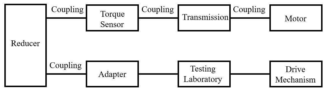
Three schemes were considered for the bench layout. The single-row layout scheme is simple in structure and clear in arrangement, but its length exceeds 10 m while its average width is less than 1 m. Since the test bench needs to be lifted to an angle of 30° when simulating formation dip, this places high demands on both the height and the length of the laboratory; moreover, for a high-load test bench, it is difficult to ensure its stability. The L-shaped scheme greatly reduces the length compared with the single-row scheme, but it also has an obvious drawback: it generates a relatively large overturning moment, which becomes a major safety hazard when the test bench is lifted to a high angle for testing. In contrast, the double-row layout scheme effectively avoids the shortcomings of the first two schemes, considerably reduces the length of the test bench, and increases its designed width, which is more conducive to the stability and safety of the test bench during operation, as shown in Figure 1.
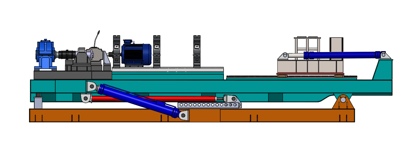
Through comparative analysis and adjustment, the finally determined design scheme mainly consists of the upper frame and lower frame of the test bench, the transmission system, the clamping mechanism, and the WOB loading system. In the transmission system, the variable-frequency motor, gearbox, flexible coupling, torque sensor, and reducer are installed on the dedicated mounting base of the transmission system in the designed transmission sequence. The overall design is shown in Figure 2.
3.2 Bench Body
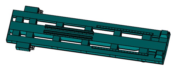
The structure of the upper frame of the test bench is shown in Figure 3, in which the cross-sectional height of the middle main beam reaches 500 mm. In the design, three main beams were adopted to ensure the strength and stiffness of the test bench while meeting the requirement on its overall width, and the main beams are connected by cross beams. At the main gravity-concentrated locations, mainly the left end where the transmission system is concentrated and the right end where gravity concentrates on the loading system and the rock block, the density of the cross beams was appropriately increased to ensure strength. Mounting seats for the guide rails of the clamping mechanism and mounting and fixing seats for the guide rails of the loading system are respectively arranged on the top of the upper frame. This design can reduce the accuracy requirement of the bench and lower the cost and expenditure.
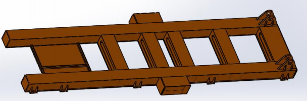
The lower frame of the test bench mainly serves to support the upper frame of the bench. The two frames are hinged through the hinge supports at the tail, so that the upper frame can rotate around the hinge points within a certain angular range, and the entire downhole tool simulation test bench is fixed to the ground. The design diagram of the lower frame of the test bench is shown in Figure 4. The reinforced hinge support is installed at the tail of the lower frame of the test bench, and in the middle position, two hinge support bosses are designed on both sides of the lower frame. These hinge support bosses directly contact the ground and are mainly used for mounting the hydraulic cylinders that lift the upper frame of the bench. Meanwhile, the two bosses increase the width of the lower frame of the test bench, which can effectively prevent the platform from overturning. In addition, multiple anchor bolt mounting holes are designed around the lower frame of the test bench to ensure that it can be firmly fastened to the ground where the bench is installed, so as to avoid the risk of overturning during tests under large inclination angles and full load.
3.3 Thrust Mechanism
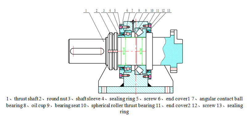
During testing, the reducer cannot withstand large axial WOB loads; therefore, a thrust shaft assembly is provided to bear the entire axial WOB. On the thrust shaft, the coupling, round nut, shaft sleeve, sealing ring, end cover, angular contact ball bearing, and spherical roller thrust bearing are assembled in sequence, as shown in Figure 5.
According to the design formula of the main shaft, the maximum shear stress τ max is generally restricted so as not to exceed the allowable stress [ τ ],thus, the strength condition is obtained as:
τ max = T max W t ≤[ τ ] (3-1)
where T max is the maximum torque and W t is the torsional section modulus of the designed shaft.
The torsional section modulus of a solid shaft is:
W t = I p R = π R 3 2 = π D 3 16 (3-2)
Therefore, the value range of the solid shaft can be derived as:
D≥ 16 T max π [ τ ] 3 (3-3)
The main shaft is designed with the commonly used steel 40Cr, whose allowable stress is 400 MPa, and the maximum torque T max is 28 kN·m. According to the formula, it can be obtained that:
D≥0.0706 m =70.6 mm (3-4)
The thrust shaft operates under low speed and heavy load, and a safety factor of 1.8 is adopted; therefore, the minimum diameter of the thrust shaft is 126 mm.
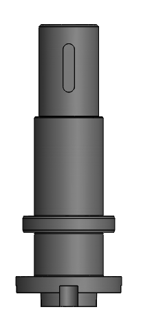
According to the finalized assembly scheme, the specific design of the thrust shaft is shown in Figure 6. At the left end of the thrust shaft, a keyway is provided for mounting the coupling and transmitting torque. Since the keyway is cut in the cross section at one end of the main shaft, it weakens the strength of the main shaft to a certain extent, so the shaft diameter should be appropriately increased. For a shaft with a diameter greater than 100 mm, the shaft diameter should be increased by 3% when one keyway is present; therefore, the diameter at the left end of the thrust shaft is designed as 130 mm. Next is the bearing mounting position, which mainly consists of a shaft shoulder for positioning and transmitting axial force and a thread mating with the round nut. At the far right end of the main shaft is a connector designed to mate with the crossover sub.
4. Simulation Analysis of Key Components
4.1 Finite Element Analysis of the Upper Frame
Since the lower frame of the test bench is connected to the ground, the downward pressure is mainly borne by the hinge support at the tail and the hinge support bosses on both sides, so the strength of the lower frame can be easily guaranteed. Therefore, the finite element analysis of the bench body is mainly carried out for the upper frame of the bench body.
The upper frame of the bench body was modeled with solid elements. The structural form is a box girder, and the selected material is Q235B with an elastic modulus of 2.1 × 10² MPa, a Poisson's ratio of 0.274, and σb = 375 MPa. The upper and lower frames of the bench body are hinged together, and the upper hydraulic cylinders are also hinged. Constraint conditions were applied to the model: fixed hinge constraints were applied to the two hinge points respectively, with all six degrees of freedom constrained. After finite element meshing, the model generated many elements and nodes. The test system has a relatively high stiffness requirement. In the calculation and analysis of the base, the lower frame is rigidly connected to the ground; for the sake of model simplification, only the upper frame was analyzed. Such a simplified calculation structure has no influence on the actual strain of the whole system.
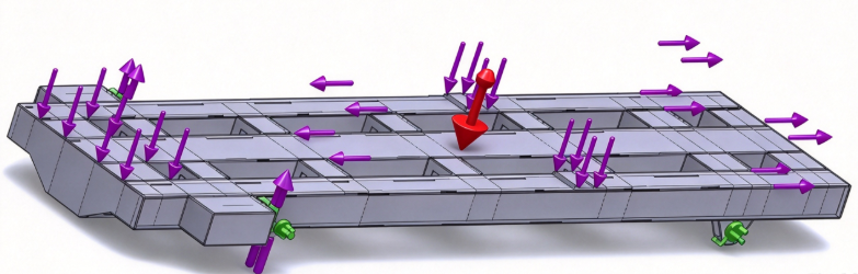
The fixed loads were directly applied to the corresponding nodes of the downhole tool simulation test bench, and the action of gravity was also taken into account in the analysis. The loading model for the finite element analysis of the upper frame of the downhole tool simulation test bench is shown in Figure 7:
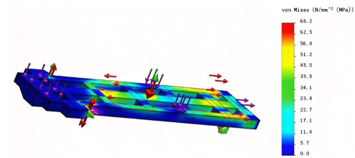
Through finite element analysis, the stress distribution contour of the upper frame of the downhole tool simulation test bench body was obtained, as shown in Figure 8. The maximum stress appears at a stiffener plate near the hinge support at the lower end, with a maximum value of 68.2 MPa. The yield strength of Q235B, the material used for the bench body, is 235 MPa; hence, the safety factor is 3.4.
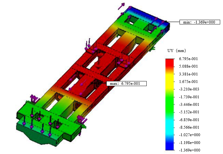
From the deformation displacement contour of the upper frame of the downhole tool simulation test bench body, it can be seen that the red area in the figure is where the bench deforms the most, which occurs at the central part of the upper frame, with a maximum deformation displacement of 0.6795 mm, as shown in Figure 9. This is mainly caused by the huge tensile force brought by the simulated WOB. Compared with the overall length of the bench, the actual deformation is extremely small and can be neglected. Through this analysis, it can be seen that the bench body with this structural design has sufficient strength to meet the test requirement of a maximum WOB of 20kN for downhole tools.
4.2 Finite Element Analysis of the Thrust Shaft
Under extreme working conditions, the thrust shaft is simultaneously subjected to the combined action of 200,000 N axial WOB and the ultimate torque, as shown in Figure 10.
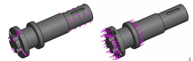
A three-dimensional solid model of the thrust shaft was established, and the boundary conditions were set according to the actual loading state. An axial reaction force of 200,000 N was applied at the contact position between the shaft shoulder and the spherical roller thrust bearing, and the ultimate torque load was applied at the input end. After solving, the stress distribution of the thrust shaft was obtained. The maximum stress appears at the back of the connector, with a maximum equivalent stress of 628 MPa. The yield strength of the steel selected for this component is 785 MPa, so the maximum stress is lower than the yield limit of the material. The stress level at the keyway is the lowest, with a minimum stress of only 0.365 MPa, as shown in Figure 11.
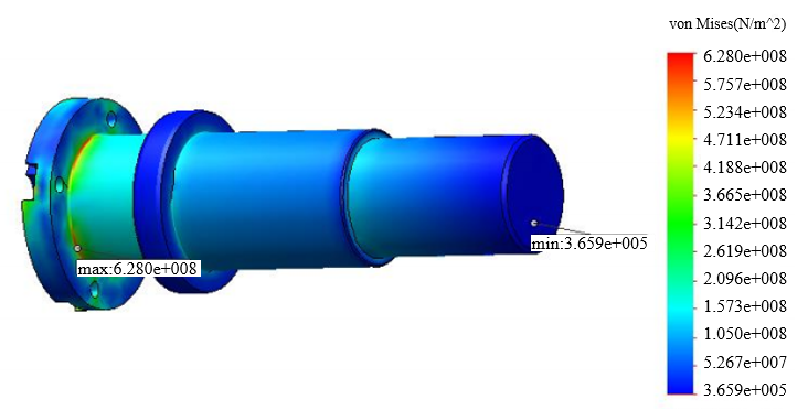
The simulation results show that under the combined static load of the ultimate WOB and ultimate torque, the thrust shaft will not undergo plastic yielding, and its strength meets the design requirements of the bench under extreme working conditions.
5. Conclusions
Aiming at the complex downhole working conditions of downhole tools, this paper completes the layout scheme of the downhole tool simulation test bench and the design of the bench body and thrust mechanism, and carries out finite element simulation verification of key load-bearing components such as the upper frame and the thrust shaft. The following conclusions are obtained:
(1) By comparing the three layout schemes, namely the single-row, L-shaped, and double-row layouts, the double-row layout was determined as the overall configuration of the bench. The bench adopts a hinged structure of the upper and lower frames; the box-girder upper frame combined with the widened anti-overturning lower frame can realize the simulation of formation dip, avoid the risk of overturning under large inclination angles and full load, and meet the clamping and loading requirements of wellbore trajectory control tools and other drilling downhole tools.
(2) The finite element simulation results show that the maximum stress of the Q235B upper frame is 68.2 MPa with a safety factor of 3.4, and its maximum deformation is only 0.6795 mm. The maximum equivalent stress of the 40Cr thrust shaft under the combined load of 200 kN WOB and 28 kN·m torque is 628 MPa, which does not reach the yield limit of the material. The strength and stiffness of the two key components both meet the extreme test working conditions with a maximum WOB of 20 t.
(3) The bench can simulate downhole working conditions such as WOB and inclination and can provide a hardware foundation for the indoor testing of downhole tools; however, it currently lacks a drilling fluid pump pressure simulation module. In the future, a drilling fluid circulation loading unit can be added to further restore the real downhole service environment and improve the multi-load coupled simulation capability of the bench, which is of engineering practical significance for shortening the R&D cycle of downhole tools and reducing field test risks.
References
- Jing Li. Development of a multifunctional testing machine for petroleum drilling and production tools[J]. Oil Field Equipment, 2011, 40(3): 92-94. DOI ↗ Google Scholar ↗
- Xiaojun Hou, Guoxin Zhu, Chonghui Cao, et al. Design and analysis of a test device for downhole tools[J]. Oil Field Equipment, 2007, 36(8): 87-90. DOI ↗ Google Scholar ↗
- Yuanchao Peng. Research on the theory and technology of closed-loop monitoring systems for rotary steerable drilling[D]. Xi'an Shiyou University, 2007. DOI ↗ Google Scholar ↗
- Tetsuo Yonezawa, Edward J. Cargill, Tom M. Gaynor, et al. Robotic controlled drilling: a new rotary steerable drilling system for the oil and gas industry[C]. IADC/SPE 74458, 2002. Google Scholar ↗
- Rongjiang Yang. Design and research of a hydraulic test bench for drilling jars[D]. Guizhou University, 2010. DOI ↗ Google Scholar ↗
- Yuchun Kuang, Heng Zeng, Xuejun Zhou, et al. Optimization design research on the hydraulic structure of PDC bits[J]. Natural Gas Industry, 2006, 26(4): 60-61. Google Scholar ↗
- Weibing Li. Scheme design of a new high-torque screw drill test bench[D]. Hebei University of Technology, 2011. Google Scholar ↗
- Cheng Yang. Research and design of the electric control system of a drill bit test bench[D]. Huazhong University of Science and Technology, 2005. Google Scholar ↗
- Sen Zhuang. Design of the data acquisition and management system of a screw drill test bench[D]. Ocean University of China, 2005. Google Scholar ↗
- Feng Ding, Wu Li, Jiawei Wang, Xuhui Liu, Hong Zhang, Hanxing Li. Research on eccentric displacement of the trajectory control tool of high build-up rate wellbore[J]. Lecture Notes in Information Technology, 2012, 9: 291-296. Google Scholar ↗
- Feng Ding, Bianyou Tan, Yongxin Yuan, Wu Li, Hong Zhang. The structure design of electromagnetic clutch in the adverse circumstances[J]. Applied Mechanics and Materials, 2011, 5: 686-691. Google Scholar ↗
- Bin Ma. Technical research on the commissioning platform of rotary steerable drilling tools[D]. Xi'an Shiyou University, 2010. Google Scholar ↗
- Jianling Zhang. A brief discussion on the modern technologies of offshore petroleum drilling machinery and tools[J]. China Science and Technology Review, 2011, (34): 194-195. Google Scholar ↗
- Peng Yang. Research on rotary deflecting drilling tools for horizontal wells with long horizontal sections[D]. Xi'an Shiyou University, 2013. Google Scholar ↗